Wednesday 11 October 2017

Rivet Bonding


We’ve seen rivet bonding grow in use for a number of years now as it spreads into more mainstream vehicles such as the Ford F-150. Mercedes, BMW and others have increased the use of this process as rivet guns and adhesives increase in quality and strength and continue proving themselves as a structural repair.
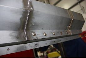
Rivet bonding is not just increasing in aluminum but steel and composites as well. This lightweight and no-heat bonding of materials offers options for manufacturing that current squeeze-type resistance spot welding (STRSW) does not.
Why So Popular?
Reducing weight in vehicles for the government CAFÉ requirements is pushing vehicle manufacturers to think of new ways of building automobiles to increase strength, lower weight and increase End of Life of Vehicle (ELV). To accomplish this goal, automakers have three basic strategies:
• New steels — Different alloys and manufacturing of parts of vehicles has dramatically increased vehicle strength and reduced overall weight. This trend shows no sign of slowing down in the years to come. Expect newer designs and stronger ultra high-strength steel and high-strength low alloy steels to come.
• Different metals — Aluminum and magnesium, along with others, are being used by themselves and in conjunction with other metals building a hybrid design of structure. The hybrid construction gives manufacturers the benefit of all materials. The welding of dissimilar metals to create a hybrid structure may not be possible.
• Alternative materials — Carbon fiber and other materials to be seen soon on vehicles will need to be bonded to other structures or materials. Limiting manufacturing to one metal or material can limit the weight savings of weight or increase in strength, which is why having multiple materials is much more beneficial to automakers. Much of the issues of the past resulted from the dilemma of how to join these different materials for these benefits. Rivet bonding is definitely the best current option as STRSW may not be an option. This is good for shops as rivet bonding can be duplicated in the field. This eliminates the argument that shops can’t duplicate OEM procedures during welding.
Why the Need?
In the past, spot welds were the easiest and most effective way to assemble automobiles. They were quick and light weight, and the steels were not as prone to cracking under stress loads or cracking from the heat of the spot weld. To use a procedure that allows the joining of any two materials together without heat damaging the desired or manufactured properties of the material is a win for vehicle manufacturers.
Heat
When combining metals using a welding process, the heat of making the weld can do damage to mechanical properties. No matter how good STRSW is, the heat from the weld causes changes. This change can create a weakness to the weld, as the heated steel is not as strong as the surrounding steel. This heat can also cause a failure over a period of time over expansion and contraction stress loads, vibration or even forces of stress from a crash. The heat also causes a corrosion hot spot as corrosion protection is burned away from the heat. This is also a potential failure of the strength of the weld.
Weld bonding is better, as the adhesive helps seal the areas being welded for better corrosion resistance. The larger surface contact of the adhesive also helps in adding strength to the forces of tensile and lap shear, reducing the stress fracture and failures of the weld. This gives strength and longevity to the weld.
Duplicating weld bonding in repairs can be difficult as many times welds need to be placed away from previous welded metal. Also, access to areas to be welded by STRSW machines could be limited. Weld bonding with gas metal arc welding is difficult as heat from the plug weld causes an issue with adhesives.
This is why MIG brazing is becoming so popular in repairs with seam welds. This low-heat brazing process gives incredible strength with very little heat that may damage the metal’s mechanical properties. MIG brazing also limits damage to the metal’s corrosion properties. The success and strength of MIG brazing lies in the amount of surface area being bonded.
Adhesive Only
I’ll probably offend some adhesive manufacturers here, so let me start by saying that adhesive bonding is awesome. I truly like the idea. The problem is it has some weaknesses. The tensile strength of adhesive for adhesive bonding is great, as is lap shear strength. However, in a crash, peel strength is a factor. When technicians remove a panel that’s weld bonded, once the welds are removed and they’re separating the panel from the inner structure, there comes a point when it “pops” off. It’s for this reason (and some others) that vehicle manufacturers limit adhesive-only bonding. If written procedures exist from the manufacturer for adhesive-only bonding, then I’m all for it. Without a written procedure from the vehicle manufacturer, I suggest following the procedure given by the OEM. Even though there’s a great amount of surface area bonding contact, there are still concerns.
Advantages
Rivet bonding addresses many issues. Although there’s a debate on whether rivets or adhesives are stronger or better, the answer to that debate is, “It depends on the application.”
As metals gain strength, they become more susceptible to damage from heat. Rivets address this. The fact that there is no heat during joining is a major plus for rivets. This, combined with the advantage of adhesive being able to be used right in the joint of the weld, also increases the strength and corrosion protection.
Rivets and adhesives working together gives a good bond in all facets of a crash. The adhesive carries major load in tensile and lap shear, while rivets prevent peeling from occurring.
Rivets
Three main rivet types are used in automotive: blind rivets, solid rivets and self-piercing rivets (SPRs). Each is used for different applications. Some simple application principles are:
• Access — depending on if a technician has access to one side or both sides of the bond.
• Flushness or appearance — If the rivet is visible or in the way of trim or other parts from attaching correctly to vehicle.
• Strength — the type of rivet and what it’s made of has a large bearing on which type to use.
• Corrosion — the material the rivet is made of is a factor for dissimilar metals. Another factor is movement. One of the weaknesses of a blind rivet is the space or movement allowed between materials. This is addressed by using SPRs or something with similar characteristics.
The type of rivet and where to place it will be determined by the OEM. Using the wrong type or style could cause problems during reassembly or after repairs are completed. In some cases, it will be a technician’s choice depending on backside access. The size of the rivet and the material it’s made of is not to be taken lightly. Vehicle manufacturers test which is best and will meet specs required to hold correctly, as well as surface contact and shear strength.
SPRs will require a special – and many times expensive – rivet gun. The application of which type and size is a critical factor. A self-piercing rivet gun will pierce the rivet through the top piece of metal and spread into the second. The shape and head will spread the rivet but not break the surface in the second layer. This tension holds the rivet and limits any movement or stresses on it, which reduces corrosion caused by movement on the rivet. This type can be used on aluminum and steels. The length of the rivet must meet specs as to the thickness of the panels. Too long or short will limit its effectiveness.
Blind and solid rivets require a pre-existing or already made hole. A blind rivet is a single side access rivet and could be used where there’s no access or limited access to the backside. A solid rivet will require access to the backside. The advantage to a solid rivet is the ability to be flush on one side. This will allow moldings and gaskets to fit back on the vehicle.
The hole, if required, also must be correct. Too big of a hole will allow too much movement, causing possible corrosion problems from contact with the base material and the removal of protective coatings by the rivet. If the hole becomes oversized, a different size or type of rivet may be required.
Adhesives
There are choices of bonding adhesives. Use the type recommended by the manufacturer. Be sure to use as directed. Some are bare metal, while others require primer. For maximum strength and corrosion protection, do not deviate from the instructions.
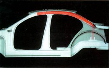
Hybrid Construction
Rivet bonding allows the manufacturers to bond dissimilar metals or even plastics to metal. The combinations are limitless as to the abilities of this type of construction. Over the years, we’ve seen structural and non-structural adaptations using rivet bonding. The adhesive strength and separating of base materials created by panel adhesives gives new abilities to engineers to combine different materials.
I’ve only covered the basics of why and how rivet bonding has become and will become more common. We as an industry have seen a lot of change in the past few years.

Tuesday 25 July 2017

Delta Spot Welding

DeltaSpot®

Resistance spot welding has established itself across a wide range of industries as a cost-effective method for joining steel sheets. In modern vehicle manufacturing in particular, high-strength steel sheets of varying strengths and quality need to be joined. This type of work is too demanding for conventional spot welding. There is also a growing need for more effective joining systems for aluminium sheet. For these types of difficult applications, manufacturers often have to turn to cost-intensive mechanical joining processes, such as punch rivets or screws. An optimised resistance spot welding process for complex, alternative applications is required. DeltaSpot® has successfully met this challenge.
Basic system principle 
The defining feature of DeltaSpot® is the robot welding gun with running process tape that runs between the electrodes and the sheets being joined. The continuous forwards movement of the process tape results in an uninterrupted process producing constant quality over a number of shifts. This results in precision in the welding process, accurate quality control and high electrode service life. Regular cap cutting of electrodes is no longer necessary. The process tape means that electrodes are effectively protected against wear and deposits from sheet coatings. This means that constant quality and reproducible welding points are assured over multiple production shifts.
Visualisation of the DeltaSpot® process: The process tape runs between the sheets and the electrodes ensuring that the electrodes are effectively protected.

Machine technology    
The process tape transfers the welding current and, at the same time, protects the contact surfaces of the electrodes from contamination by zinc, aluminium or organic residues. This protection results in a significantly increased service life for electrodes. Tests with aluminium sheets (AlMg3 alloy) showed an extremely long service life of approx. 30,000 welding points. The process tape provides indirect sheet contact producing a largely spatter-free welding result. It eliminates the otherwise unavoidable rework necessary to meet new quality standards. The coating of the process tape has proved to be particularly advantageous for aluminium sheets. Optimised contact with the aluminium material prevents spattering and the associated damage to components. The process tape needs to be replaced infrequently and this takes little time and effort. In normal use, the process tape produces 7,000 welding points. If every segment of the welding tape is used two or three times, the service life can be extended accordingly.
The process offers additional features to the physical properties already described. These includes the servo-electric holder drive that saves on expensive compressed air supplies, and the integrated software that provides central configuration of the individual welding guns. The comprehensive monitoring and diagnostics system is also integral. When the welding process is complete, the tape contact surfaces used provide information on the work process. Image recording systems detect this unique fingerprint of the welding point. Suitable analysis systems can analyse this data. The software has a central role to play in this. The quality assurance system that can be integrated as an option enables complete recording of process data and thus reduces subsequent time-consuming quality control.

Application and advantages          
DeltaSpot® is primarily suitable for steel and aluminium sheets. It can also be used in combination with commonly used anti-corrosion coatings and for black/white joints. The latter are unalloyed or low-alloy steel joints with non-rusting, high-alloy steels. Different material combinations and thicknesses are also possible. Examples include deep-drawn steels in combination with chrome-nickel steels or Usibor, as well as material combinations with coated steel sheets and aluminium. Development focused mainly on the applicability of the process for high-alloy steel joints as well as magnesium joints. These materials provide the greatest potential in modern lightweight construction. Two-sheet or multi-sheet joining of practically all the above material combinations can also be achieved. The same welding gun can be used to weld different sheet thicknesses and material combinations simply by changing the process tape.
The high efficiency level is produced by additional process heat that arises as a result of the internal resistance and the contact resistances of the process tape. For traditional resistance spot welding of 2 x 1.0 mm AlMg3 sheets, a current of 35,000 A to 40,000 A is required. The process tape reduces the current to 16,000 A. The low welding current and the individual adaptation of the process tape to the welding process permit controlled heat application and allow the position and shape of the welding point to be controlled. This is described in further detail below.
Three-sheet joints (two thick sheets and one thin sheet) are problematic for traditional spot welding. The welding point forms in the area of the thicker sheet and does not cover the thin sheet sufficiently. To compensate for this effect, the additional heat applied by the process tape ensures targeted control of the welding point depth. This means it is possible to compensate for the reduced amount of heat in the area of the thin sheet by using a process tape with greater resistance. In this way, the welding point is displaced sufficiently towards the thin sheet. At the same time, the shape of the welding point is symmetrical and will now show increased volume in the area of the thinner sheet.

With aluminium, there is the problem of high electrical and thermal conductivity and a correspondingly low electrical resistance. The accompanying limited heat generation can also be compensated for by selecting the correct process tape. In contrast to traditional spot welding of aluminium that until now has been virtually impossible to achieve, the new resistance spot welding process can successfully weld aluminium for the first time.

Summary   
To summarise, the spot welding with tape process is expected to find a wide range of applications in joining technology. Last but not least, the DeltaSpot® process promises to offer new perspectives for innovative working and opportunities for cost saving particularly in vehicle manufacturing.


Monday 24 July 2017

AOMS ON OFFER to conform with BSI 10125

IMI Accreditation-AOM 009.

As you are all aware IMI Accreditation has developed a new route structure for re-accreditation.
What changes for you?
The simple answer to this question is very little. The reason for this is the IMI has chosen to mirror the current British Welding Standards. This means we can carry out the first steps towards your re-accreditation ON SITE.
What does this mean to you and your technicians?
The new AOM 009 (BS1140 & BS4872) has officially become the recognised starting point for renewing an IMI Accreditation ID card.
Once technicians have passed this new AOM they can proceed with the rest of their IMI Accreditation Panel re-accreditation.
This module is used as a prerequisite but unlike your IMI Accreditation your AOM-009 is like your current British standard. It has a 2 year validity period.
How does this help you?
First and foremost a reduction in cost. The reason for this is that there is no need for multiple testing for both ATA and BSI10125.
As this certification can be carried out on site there is no need to send your technicians off site incurring unnecessary costs i.e. travel, overnight expenses and reduced loss of production.
The certification being carried out on site has a number of advantages. Your technicians will be in a familiar working environment and the equipment they use will not be alien to them.

IMI Accreditation-AOM 030


What is this?

AOM-030 we give your technicians a standardised sill section individual to the delegates, this removes the risks of overworked areas of a vehicle clashing.


The AOM-030 Sill section repair will be carried out in the work place. This will give the technician the best possible chance of achieving the desired standards.


This module is about the replacement of a welded section within the construction of a vehicle bodyshell. The candidate will be required to cut a specified section from a welded panel (i.e. a sill section) without causing damage to other vehicle systems or the vehicle structure. The candidate will cut a section from a new panel and replace the section into the vehicle body using techniques such as spot welding, MAG welding, bonding, riveting, and MIG Braze. The candidate must be able to ‘dress’ the welds to a finish where the repaired section is ready to accept body filler to a depth of no more than 2mm. The candidate must access the correct repair information / specification and use this information to carry out the repair to the vehicle bodyshell. Note that this exercise will mainly be carried out on a rig, but the competence required will be similar to those used when repairing a vehicle body shell.

IMI Accreditation-AOM 028


IMI are pleased to announce that AOM 028 is now available as a standalone module. This module provides another option for accident repair workshops to be compliant with the requirements of BS10125, in relation to bonding and mechanical fastenings.
AOM 028 is about the replacement of a welded section, within the construction of a vehicle body shell. The candidate will be required to cut a section from a new panel and replace the section into the vehicle body using techniques such as spot welding, MAG welding, bonding and riveting.


Industrial lasers and applications in automotive welding

Makes for interesting  reading


Industrial lasers and applications in automotive welding

S T Riches, TWI
This paper was presented on 22 October 1998 at a Make It With Lasers TM Workshop entitled Lasers in the Automotive Industry, held at Nissan Motor Manufacturing (UK) Ltd, Sunderland.

Introduction

The use of lasers in automotive manufacture has increased dramatically over recent years to a position where about 15% of all industrial processing lasers are installed in production. Although the lasers are devoted mainly to cutting applications, a significant and growing proportion of lasers is being applied to welding. In a survey in 1992, about 20% of the lasers installed in the automotive industry were used in welding applications. [1] Since that time, there has been an explosion of growth in welding applications, particularly involving steel manufacturers, for tailored blank manufacture and in body-in-white welding applications.
This paper will review the industrial laser types which are available for welding applications, then describe the range of current applications used in the automotive industry and highlight areas where developments in processing techniques and equipment are poised to make an impact for laser welding in the future.

Industrial Laser Types

There are two main types of industrial laser of interest to structural fabrication; CO 2 and Nd:YAG lasers. The lasers have different characteristics that are summarised in Table 1.
Table 1. Summary of characteristics of CO 2 and Nd:YAG lasers
PropertyCO 2 laserNd:YAG laser
Lasing mediumCO 2 +N 2 +HeNeodymium doped yttrium
aluminium garnet crystal rod
Radiation wavelength10.6µm1.06µm
Excitation methodElectric dischargeFlashlamps
Efficiency5-10%2.5-5%
Output powersUp to 60kWUp to 4kW
Beam transmissionPolished mirrorsFibre optic cable
High power CO 2 lasers are predominantly used for the welding of automotive components, such as gears and transmission components, which require circular and annular welds and in tailored blank applications. The majority of lasers have a power of 6kW or less.
High power Nd:YAG lasers are now available at workpiece powers of 4kW, which have fibre-optic beam delivery. The welding applications are concentrated in body-in-white assembly. Higher power equipment is likely to be developed in the next 2-3 years and there are likely to be improvements in the efficiency of Nd:YAG lasers with the arrival of diode pumped Nd:YAG lasers.
Within the laser industry, one of the main advances in the past two years has been in diode lasers (wavelength 0.8-0.9µm), where 2kW systems are now commercially available. However, at the current status of development, the power densities required for welding of sheet materials used in the automotive industry (about 1x10 6 W/cm 2) have not been achieved. Research work is underway in Germany to develop diode lasers and their applications and this situation may change in the next 3 years.

Laser Welding in the Automotive Industry

Welding of Automotive Components

The applications of laser in the manufacture of components cover engine parts, transmission parts, alternators, solenoids, fuel injectors, fuel filters, air conditioning equipment and air bags. An example of a laser welded solenoid is shown in Fig. 1. and gear component is shown in Fig. 2. The attractions of laser welding for these applications are the ability to weld pre-machined precision components with restricted heat input and minimal distortion [2] . This enables weight savings to be made through the use of thin walled assemblies and optimisation of the compactness of the component.
Fig. 1. CO 2 laser welded solenoid.
Fig. 2. CO 2 laser welding of gear component.
In industrial production, the advantages of the laser welding process have been established compared to alternatives such as electron beam welding. This is due mainly to the high productivity and small amount of down-time compared to vacuum based systems and the subsequent reduced manufacturing costs [3] . However, there is a need to spend a high amount of effort on component preparation and high precision of component handling and beam transmission is required. [4]
Most automotive manufacturers have invested heavily in CO 2 laser technology for these types of applications and most of the issues relating to the production of millions of components have been resolved. Developments have focused on expanding the range of material combinations which can be welded using lasers, including joining of cast irons to steels through the use of wire feed techniques and optimisation of the procedures to harden components whilst avoiding problems with cracking due to high carbon levels in the weld zone.

Welding in Automotive Body Assembly

For the past 40 years, welds in mass produced automotive body parts have been almost exclusively fabricated from pressed steel sheets and joined using resistance spot welding. The potential benefits of implementing laser welding technology are numerous - advantages may be gained in respect of single sided access, reduced flange widths, increased torsional stiffness (thus leading to improved vehicle structural performance and/or down gauging of material thickness), smaller heat affected zones and less thermal distortion, high speed automated processing and design flexibility (eg. in multi-layer joints).
Extensive work has been performed worldwide to realise the potential of laser welding for automotive body manufacture. As the turn of the century approaches, the number of systems installed in production is increasing, where two main types of laser welding are being employed. The first is a direct replacement for resistance spot welding or adhesive bonding, where lap joints or hem flange joints are utilised on pressed components for body-in-white assembly. The second is the laser butt welding of flat sheets (which may be dissimilar thickness or material grade), which are subsequently formed into pressings. The pressings are called "tailored blanks" and the widespread acceptance of this technology has spawned a number of companies and enterprises associated with steel producers to meet the demands of the automotive industry in addition to in-house manufacture.

Body-in-white applications
The implementation of laser welding of sheet assemblies as a replacement for resistance spot welding is growing, where welding of the roof to side panel is one of the most common applications. [5,6] This component is normally a two layer lap joint in zinc coated steel, with periodic three layer thicknesses to be welded, over lengths of 2.5-3m. One of the main challenges for laser welding of these types of joints is the presence of the zinc coating at the interface between the sheets, where the low vaporisation temperature of the zinc (906°C), can cause problems with weld consistency due to the formation of blowholes and porosity, if the sheets are tightly clamped together. Various approaches have been adopted to overcome this problem including:
  • Roller clamping systems which create a gap at the interface
  • Stamping of dimples in the steel pressings of consistent depth
There are both CO 2 and Nd:YAG lasers in production for this kind of application, and it is forecast that Nd:YAG laser applications will grow due to the flexibility of the fibre optic beam delivery as higher powers become available. A recent review of laser applications at BMW has indicated that 9-11m of laser welding is carried out on certain models [7] and the ULSAB project [8] has used over 18m of laser welding in its concept structure.
Fig. 3. Lap joint in 1.6mm thick 5754 aluminium alloy sheet welded at 5m/min with CO 2 laser
Laser welding is also being applied in the production of partial penetration welds, for example, in hem flanges often used in doors, bonnets, boot lids and other closures [9]. Although the majority of work performed has been on steel sheet, there have been a number of programmes conducted on aluminium alloys. [5] The laser welding of aluminium alloys is more difficult than for steel, due to the high reflectivity and thermal conductivity of the material, the low viscosity of liquid aluminium and the tendency for cracking and porosity in welds in certain alloys. Extensive work over the past 10 years has demonstrated the feasibility of laser welding of aluminium alloys using CO 2 and Nd:YAG lasers, where once a threshold power density is exceeded for a particular alloy, keyhole welding can be established and seam welds can be produced with similar welding speeds to steel sheets, see Fig. 3.

Fig.4. Tailored blank in door inner panel

Tailored blank welding

The principle of using laser welded tailored blanks in automotive manufacture started with the production of a two piece floor pan for Audi. Since that time, the applications for tailored blanks have grown significantly as it has been gradually realised that tailored blanking is a cost effective method of manufacturing whilst achieving weight savings. The main advantages stem from the ability to join materials of dissimilar thicknesses and grades (thus allowing weight/strength to be placed where required), the improved utilisation of material from steel strip and the high degree of automation possible. These advantages have enabled a reduction in the number of pressing operations through the elimination of reinforcements, for example, which have more than compensated for the cost of manufacture of the tailored blanks. The types of application for tailored blanks are expanding and include rails, panel rockers, panel skirts, door inners (Fig. 4.), body side outers and, in the ULSAB concept vehicle, ne
In the manufacture of tailored blanks, the two main points of debate centre on the preparation of the edges for welding and the choice of laser type. For the edge preparation, there is a desire to use standard blanked edges but this normally requires special clamping or welding systems to ensure that the blanks can be welded consistently. The clamping systems developed include using side pressure on the fixtures or using a roller system to deform the sheet adjacent to the weld to bring the sheet edges into intimate contact (<0.1mm gap). The welding systems employed where the gaps between the sheets are >0.1mm include beam weaving or twin spot welding, but this generally reduces the maximum welding speeds that can be achieved. The use of precision re-shearing of the edge prior to welding within a blank welding system is claimed to improve weld consistency as the cross-sectional area of the joint is guaranteed and the welding speed can be maximised. [10]
For the choice of laser type, the established technique is the use of CO2 lasers and automated production systems normally have a 5-6kW laser. With the development of Nd:YAG lasers with workpiece powers of >3kW, a number of production systems have been installed for tailored blank manufacture, with claimed advantages of increased versatility due to the fibre optic beam delivery, higher welding speeds (due to the improved coupling of the laser wavelength), improved tolerances to gaps and negation of the need for gas shielding. [11] In a similar manner to the edge preparation, the economics of manufacture is complex and will have to be resolved on a case by case basis.
Fig. 5. Bulge test in laser welded aluminium alloy tailored blank
Low carbon and high strength steel sheets in thicknesses between 0.7-2mm are used with few reported problems, provided that the welds are located in positions where the weld is not subjected to much movement across the weld line during forming. For chassis and sub-frame components, where thicknesses of steel sheet are generally between 2-4mm and yield strengths are up to 400MPa, there is a similar desire to implement tailored blank technology, but the selection of steel type is more critical to attain the required formability. [12]
There is a growing interest in the exploitation of aluminium alloys for tailored blank application, [11] but the laser welding is more critical as the weld line is a zone of weakness, see Fig. 5. Developments have focused on the application of wire feed and twin spot welding to improve weld quality and consistency.

Laser cutting/welding

Lasers are capital intensive tools and, in order to ameliorate the costs, systems should be utilised to maximise their production capacity. One method of achieving this is to use one laser source for cutting and welding. This principle has been demonstrated industrially in the manufacture of a C column, where two zinc coated steel sheets are overlaid in the clamping system and then laser cut. The cut edges are then re-positioned and welded together in a butt joint configuration using filler wire additions. [13] For this application, the main advantage is the achievement of a high quality weld which requires minimum finishing to produce a Class A surface.

Future Automotive Laser Welding Applications

Whilst it is predicted that the above automotive laser welding applications will grow, in some cases, at a substantial rate, there are other components and materials that will benefit from the advantages of laser welding. Listed below are some of the topics where laser welding is poised to make an industrial impact:
  • Pressed components to hydroformed tubes or extrusions
  • Production of tailored hydroformed tubes or other stiffened structures consisting of welded sheet
  • Production of node structures in aluminium alloy castings/extrusions or extrusions/extrusions
  • Welding of magnesium alloy components
The success of these applications will ultimately depend on the weight, performance and cost advantages that can be demonstrated for high volume manufacturing scenarios.

Concluding remarks

Laser welding has "come of age" for automotive manufacture, where it is an established technique for automotive components, tailored blanks and body assembly. The main advantages to be gained through the use of laser welding include low distortion, single sided access, high torsional stiffness of components, and cost savings through elimination of other manufacturing operations. Most of the applications to date have focused on welding of steels but there is a growth in confidence in laser welding of aluminium alloys.
The advent of high average power Nd:YAG lasers, delivering over 3kW power to the workpiece, will make an increasing impact on the type of laser welding systems installed in production, but there will be considerable pressure to reduce capital costs and improve efficiencies of the laser source. Competition will also be fierce from CO 2 laser manufacturers and non-laser processes in this significant market.

Monday 17 August 2015

High-strength low-alloy steel


High-strength low-alloy steel (HSLA) is a type of alloy steel that provides better mechanical properties or greater resistance to corrosion than carbon steel. HSLA steels vary from other steels in that they are not made to meet a specific chemical composition but rather to specific mechanical properties. They have a carbon content between 0.05–0.25% to retain formability and weldability. Other alloying elements include up to 2.0% manganese and small quantities of copper, nickel, niobium, nitrogen, vanadium, chromium, molybdenum, titanium, calcium, rare earth elements, or zirconium. Copper, titanium, vanadium, and niobium are added for strengthening purposes. These elements are intended to alter the microstructure of carbon steels, which is usually a ferrite-pearlite aggregate, to produce a very fine dispersion of alloy carbides in an almost pure ferrite matrix. This eliminates the toughness-reducing effect of a pearlitic volume fraction yet maintains and increases the material's strength by refining the grain size, which in the case of ferrite increases yield strength by 50% for every halving of the mean grain diameter. Precipitation strengthening plays a minor role, too. Their yield strengths can be anywhere between 250–590 megapascals (36,000–86,000 psi). Because of their higher strength and toughness HSLA steels usually require 25 to 30% more power to form, as compared to carbon steels.

Copper, silicon, nickel, chromium, and phosphorus are added to increase corrosion resistance. Zirconium, calcium, and rare earth elements are added for sulfide-inclusion shape control which increases formability. These are needed because most HSLA steels have directionally sensitive properties. Formability and impact strength can vary significantly when tested longitudinally and transversely to the grain. Bends that are parallel to the longitudinal grain are more likely to crack around the outer edge because it experiences tensile loads. This directional characteristic is substantially reduced in HSLA steels that have been treated for sulfide shape control.

They are used in cars, trucks, cranes, bridges, roller coasters and other structures that are designed to handle large amounts of stress or need a good strength-to-weight ratio. HSLA steel cross-sections and structures are usually 20 to 30% lighter than a carbon steel with the same strength.

HSLA steels are also more resistant to rust than most carbon steels because of their lack of pearlite – the fine layers of ferrite (almost pure iron) and cementite in pearlite.[citation needed] HSLA steels usually have densities of around 7800 kg/m³.


Wednesday 19 November 2014

Hydroforming do you know what you're dealing with on todays cars?


Lightweight vehicles are big news in the automotive industry at the moment, following the launch of the ultralight steel. Lighter vehicles offer the benefits of materials and energy savings, and so are more environmentally friendly. But weight cannot be trimmed from a car without design changes, which is why new ways of producing lightweight steel components - and of reducing the total number of components - are vital for the future. One such technique, is hydroforming.

What is Hydroforming?

Hydroforming uses fluid pressure in place of the punch in a conventional tool set to form the part into the desired shape of the die (figure 1). The technique is very useful for producing whole components that would otherwise be made from multiple stampings joined together. For example, a typical chassis component that would normally be made by pressing up to six channel sections and joining by spot welding can be hydroformed as a single part. Considerable mass savings are possible through eliminating the flanges required for welding and using thinner steel. Yet stiffness is maintained owing to the elimination of the discontinuous spot-welded joints.

Acceptance of Hydroforming

Hydroforming is already widely used - in the US, more than a million engine cradles a year are produced by hydroforming processes, and in Europe the technology is being used in sub-frames for models such as Ford’s Mondeo and General Motors’s Vectra. Some 2.8 million components a year for one of Chrysler’s model are produced by hydroforming, too. However, as hydroforming - particularly high-pressure hydroforming - is at the frontier of modern steel technology, many designers and engineers still need convincing of its capabilities.

Types of Hydroforming

There are four main types of hydroforming:
•        Hydroforming of tubes, usually at low pressure, is the most widely used technology at present, with hydroformed tubular parts offering improved integrity and structural performance.
•        Low pressure hydroforming simply re-shapes tubes, producing a very good shape, but is not as useful if better cross-section definition is required.
•        High-pressure hydroforming, totally changes the tube shape and alters the length to circumference ratio by up to 50%. It gives very good tolerance control, being a highly robust process.
•        Panel hydroforming at high pressures is used in the aerospace industry, and is expected to be used for applications in the automotive industry in which hydroforming is needed to get the right material flow.

Hydromechanical Forming

Meanwhile, hydromechanical forming has a rapidly developing future in the manufacture of tight panels, such as roof panels. The process produces essentially flat panels with a controlled degree of deformation and tightness. Hydraulic pressure is used to expand the material into the die set with uniform strain. The punch then comes down to re-deform the metal into the required flat panel.

Pillow Hydroforming

‘Pillow’ hydroforming uses hydraulic pressure to form a component from two steel sheets that have been welded around their perimeter. This allows the hydroforming of pillars that need to be slim at the top and wider at the bottom, for example. It also makes it easy to leave a weld flange for subsequent assembly.

Obstacles to Widespread use of Hydroforming

One of the biggest obstacles to the more widespread use of hydroforming lies in persuading people of its benefits. Designers and engineers used to working with press-tools find it difficult to grasp the principles of hydroforming (although those with knowledge of plastic moulding can more readily accept it). If hydroforming is to be used in more than just a few specific components, there must be a whole new approach to the design and architecture of a vehicle. As one leading industry figure says, “if companies design for hydroforming, then it will be more widely used. But that is the whole point - design concepts have to be changed when considering this technology”. This view is echoed by an industry research specialist, “it has to be very carefully designed for. Most of the applications of high-pressure hydroforming I see are very poor - they are not recognising its full potential”.
However, change is coming - particularly in Germany where hydromechanical forming is well advanced. The twin demands for lower weight and high strength are likely to drive the switch to hydroforming at an increasing rate. In the UK and continental Europe, high volume manufacturing is geared towards making panels with traditional presswork processes. The amount of capital tied up in presswork technology is inhibiting automotive companies from adopting hydroforming for production of the ‘body-in-white’. Another factor is that, taken in isolation, hydroforming is relatively expensive.

Benefits of Hydroforming

However, the ULSAB study - in which British Steel is a participant - shows the way forward with its side roof rails being produced by hydroforming, figure 2. The rails are single hydroformed components that replace up to eight press-formed components (each of which requires a tool and die set) and eliminate costly sub-assembly. The rails are lightweight and structurally much more efficient than the conventionally constructed parts. In this example, productivity and cost benefits mean hydroforming is clearly favoured. It also shows that hydroforming gives the greatest benefits when it is used to integrate components or functions as part of a holistic design process.
Figure 2. Hydroformed side roof rail indicates in red.
Hydroforming is more than just another way of creating a component. Hydroforming alters the functionality of components and assemblies, and this may have consequences on the design of the rest of the structure. The potential benefits of applying hydroforming should be considered early in the design process.

Achieving the Benefits of Hydroforming

To achieve the benefits cost-effectively, designers need to work in partnership with experts who have specialist knowledge of hydroforming, including hydroforming machine manufacturers and - very importantly - materials suppliers who are able to provide expertise on tube manufacture with an emphasis on high strength ductile steels. New tube making techniques are needed so that high strength steels can be used to make the higher diameter/thickness ratios required for lightweight applications. The current tube manufacturing techniques can only produce tubes with a diameter/thickness ratio of 60:1.

Areas that can Benefit from Hydroforming Techniques

Another area ripe for exploitation is lightweight applications for hydromechanically formed panels and other components made using ‘pillow’ forming techniques. Any structural component composed of inner and outer panels can be re-engineered as a ‘pillow’ hydroformed structure, ranging from a door to a complete body side. The technology can also be used for making shaped containers to fit neatly into available spaces, such as fuel tanks, washer reservoirs and overflow containers.
There is great potential for these panels and for hydromechanical forming in the creation of key components such as floor pans, van body sides and body roof panels. The hydroforming of such components will provide weight savings in combination with improved performance.

Summary

In general, hydroforming is a technically elegant process. It is also a much more robust and practical process than many in industry will admit, and this robustness alone will ensure its increasing use. But, aside from the cost, one sticking point remains. Hydroformed components require different assembly techniques because single-sided welding is necessary. So engineers developing a total supply chain, incorporating the welding robots, must also adapt to allow the introduction of hydroforming.
Continuous fusion welding, which is a slow process with a large heat-affected zone, or automatic laser welding are both suitable joining techniques for hydroformed components. Laser welding is already used in non-critical parts of a car body structure, such as joining the roof panel to the roof rail. The technology has a high initial cost, but benefits include on-line inspection using the laser beam. Work on the laser welding of hydroformed components is being carried out at British Steel's Welsh Technology Centre, where the UK’s first high-pressure hydroforming machine was commissioned earlier this year.
The benefits hydroforming can bring to the industry are, without doubt, tremendous. But to profit from them, designers and engineers throughout the production process must be prepared to change both their ways of working and their thinking

Wednesday 24 September 2014

Proud sponsor of Northampton Old Scouts

RPM Welding is a proud to be sponsoring 2 players from Northampton Old Scouts for this coming season.


Good Luck from all at RPM